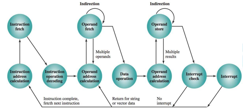
< Instruction Life Cycle >

< 1. Fetch Stage >

In this stage, the processor retrieves the instruction from memory. The memory address of the instruction is usually stored in a Program Counter (PC), which is a register that keeps track of the address of the next instruction to be executed.

  • The CPU reads the instruction stored at the memory location specified by the Program Counter (PC).
  • The instruction is fetched from RAM or cache memory.
  • The Program Counter (PC) is incremented to point to the next instruction in sequence.
Key Components Involved:
  • Program Counter (PC): Holds the address of the next instruction.
  • Instruction Register (IR): Temporarily holds the instruction that has been fetched from
  • memory.

< 2. Decode Stage: >

In this stage, the processor decodes the fetched instruction to determine what action needs to be performed. This involves interpreting the opcode (operation code) and identifying the operands or data required for execution.

  • The instruction fetched into the Instruction Register (IR) is broken down.
  • The opcode is decoded to identify the operation to be performed (e.g., addition, multiplication, load, jump)
  • Any operands (e.g., registers or memory locations) are identified and prepared for execution.
  • The necessary control signals are generated to carry out the instruction.
Key Components Involved:
  • Control Unit (CU): Interprets the opcode and generates control signals.
  • Decoder: A part of the control unit that decodes the instruction.

< 3. Execute Stage >

This is the stage where the actual operation specified by the decoded instruction takes place. Depending on the type of instruction, this can involve arithmetic operations, logical operations, data movement between registers, or branch operations.

  • If it's an arithmetic or logical instruction, the Arithmetic Logic Unit (ALU) performs the operation (e.g., ADD, SUB, AND, OR).
  • If it's a data transfer instruction, data is moved between registers or between memory and a register.
  • If it's a jump or branch instruction, the Program Counter (PC) is updated to reflect the new instruction address.
Key Components Involved:
  • Arithmetic Logic Unit (ALU): Performs arithmetic and logical operations.
  • Registers: Temporary storage locations for data and operands.
  • Control Unit (CU): Manages execution flow based on the decoded instruction.

< 4. Memory Access Stage (Optional) >

For instructions that involve reading from or writing to memory (e.g., LOAD, STORE), a memory access stage is necessary.

  • If the instruction requires reading from or writing to memory, the memory address is accessed, and the necessary data is transferred to or from memory.
  • For LOAD instructions, data from memory is read into a register.
  • For STORE instructions, data from a register is written to memory.
Key Components Involved:
  • Memory Unit (RAM): Used for reading and writing data.
  • Address Bus: Carries the memory address.
  • Data Bus: Carries the data to and from memory.

< 5. Write-back Stage (Optional) >

In some cases, the results of the executed instruction need to be written back to a register or memory. For example, if an arithmetic operation results in a new value, that value must be written back to a register.

  • The result of the execution is written back to a register (or memory if necessary).
  • This is typically the final step in the life cycle for operations like arithmetic calculations or data manipulation.
Key Components Involved:
  • Registers: Store the final result of the instruction.
  • Control Unit (CU): Coordinates the writing-back process.

< 6. Interrupt Handling (If Applicable) >

  • Interrupt Handling is a special phase that occurs whenever an interrupt is detected during any of the earlier stages. The processor must check whether an interrupt request has occurred.
  • Interrupt Request: An interrupt can come from hardware (e.g., a device requesting I/O) or software (e.g., an exception like a division by zero).
  • Interrupt Service Routine (ISR): If an interrupt is detected, the processor saves its current state (such as the program counter and other registers), so it can return to the interrupted instruction later. The processor then jumps to an Interrupt Service Routine (ISR) or interrupt handler, which is a special function designed to handle the interrupt.